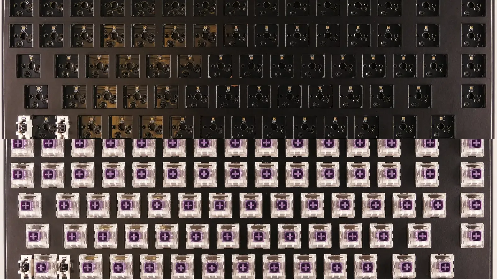


Building a custom mechanical keyboard is less about having rare tools and more about checking compatibility, working in the right order, and testing before you hide anything inside the case. This guide walks you through a reliable first build, whether your kit uses hot-swap sockets or soldered switches.
You do not need to tune every part on day one. A compatible kit, a calm workspace, and a test at each stage will get you much further than an expensive pile of upgrades.

Before you buy: check compatibility
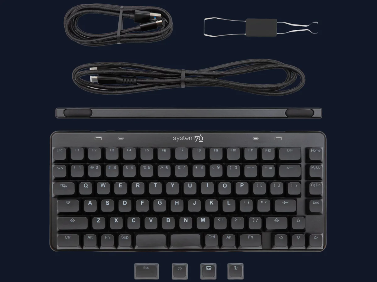
A custom keyboard is a system. The case, PCB, plate, stabilizers, switches, and keycaps must agree on layout and mounting details.
Use this checklist before opening a package:
- Layout: Confirm the exact size and layout, including split backspace, right Shift, bottom row, and ISO or ANSI support.
- PCB and case: Verify that the PCB mounting points, screw locations, USB cutout, and daughterboard connector match the case.
- PCB and plate: Check that the plate supports your PCB’s layout. A plate can omit positions that the PCB supports, or add positions the PCB cannot use.
- Switch interface: A hot-swap PCB accepts switches without soldering, but the socket type and switch footprint still matter. A soldered PCB requires a soldering iron and compatible through-hole switch pins.
- Stabilizers: Confirm whether the board needs PCB-mount, plate-mount, screw-in, clip-in, or a specific layout of stabilizers.
- Keycaps: Make sure the set contains the right modifiers and spacebar size for your layout. A standard 6.25u spacebar will not replace every 7u or split spacebar arrangement.
- Firmware: Check whether the PCB is supported by its stated firmware, such as VIA or QMK, and whether a keyboard definition or firmware file is required.
Compatibility rule: If a product page does not clearly state the supported layout, mounting style, and dimensions, treat it as unverified. Do not assume that parts with the same percentage size will fit together.
What you need
Must-have tools
- Keycap puller, preferably a smooth wire style
- Switch puller if the PCB is hot-swappable
- Small Phillips or hex drivers that fit the kit screws
- Fine tweezers for stabilizer parts and bent switch pins
- A known-good data USB cable, not a charge-only cable
- Bright, stable lighting and a clean, soft work surface
- Small trays or cups for screws and stabilizer parts
Needed for soldered builds
- Temperature-controlled soldering iron with a fine tip
- Suitable electronics solder and a brass wool or damp sponge tip cleaner
- Fume extraction or good ventilation
- Eye protection and a heat-safe stand
- Flush cutters for trimming switch leads
A soldering iron is hot enough to burn skin, melt plastic, and damage a PCB. Keep the iron in its stand when not in use, never work beside flammable materials, and unplug the board before inspecting or correcting a joint.
Optional enthusiast tools
A switch opener, small brush, switch lubricant, stabilizer grease, flush cutters, a multimeter, a desoldering pump, and a switch tester are useful when you plan to tune or repair keyboards. They are not required for a straightforward hot-swap build.
Components checklist
Before assembly, identify every part and compare it with the kit’s build guide:
- PCB and, if present, daughterboard and JST cable
- Case pieces, gaskets, foam, feet, and mounting hardware
- Plate, if the design uses one
- Stabilizer kit for every large key position
- Switches that match the PCB footprint
- Keycap set with the correct layout support
- Firmware instructions or a VIA/QMK definition
Lay the parts out in groups. Photographing the kit before you begin is a simple way to remember screw locations and cable orientation.
The safest build order
The order below minimizes rework and makes faults easier to isolate:
- Inspect parts and confirm compatibility.
- Test the bare PCB and firmware connection.
- Prepare and install stabilizers.
- Join the plate and PCB with a few switches, or prepare the soldered assembly.
- Install and test all switches.
- Connect the daughterboard or USB assembly, then place the PCB in the case.
- Close the case without over-tightening screws.
- Install keycaps and run a final matrix, stabilizer, and firmware test.
Step 1: inspect the parts
Look for cracked acrylic, missing screws, bent plate edges, loose hot-swap sockets, damaged USB connectors, and stabilizer wires that are visibly kinked. Do not power a PCB that has conductive debris, wet cleaning fluid, or a damaged connector.
Check that the plate cutouts match the intended layout. A common first-build mistake is discovering that the keycaps support ANSI while the PCB and plate were configured for ISO, or that a split key requires a different stabilizer arrangement.
Step 2: test the PCB before assembly
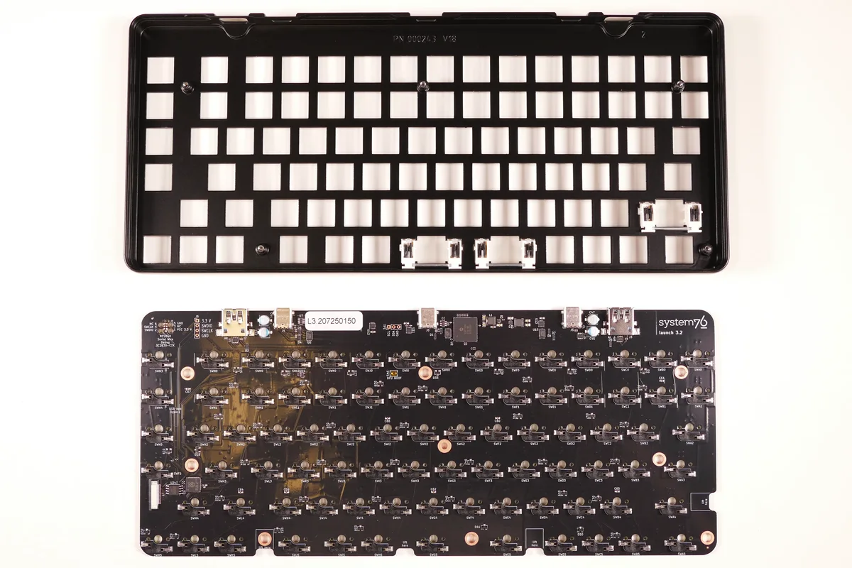
Allow 10 to 20 minutes. This is the most valuable step in the whole build. A bare PCB is easy to replace or troubleshoot. A PCB buried under switches, foam, and a case is not.
Test procedure
- Place the PCB on a non-conductive surface such as its packaging or a clean desk mat.
- Connect it with a known-good data cable. If the board has a detachable daughterboard, test the complete cable path recommended by the kit.
- Open a keyboard tester, or use the board’s supported VIA/QMK tool. If the board is not detected, read its firmware instructions before assuming it is defective.
- If the kit documentation permits this test, briefly bridge the two switch-contact pads with fine tweezers or a bent paper clip. Touch only the intended pads and use light pressure.
- Confirm that the expected key appears in the tester. Test every position, including the corners, navigation cluster, and stabilizer-adjacent keys.
- Record any failure by row and column. Repeat a failed position once to rule out a poor contact.
- Disconnect the USB cable before changing anything on the PCB.

PCB testing safety and troubleshooting
- Never drag metal across several pads. A brief, controlled touch is enough.
- Do not use a powered PCB on a metal table or on top of loose screws.
- If no keys register, try another data cable and port, then check whether the board needs a reset or firmware flash.
- If only one socket fails on a hot-swap board, inspect the socket solder joints and the switch contact path. Do not push harder.
- If several keys in one row or column fail, suspect firmware, a connector, or a PCB trace rather than several switches at once.
- If the PCB becomes hot or smells unusual, disconnect it immediately and stop troubleshooting until the cause is understood.
Step 3: install and tune stabilizers
Stabilizers support the spacebar, Shift, Enter, Backspace, and numpad keys. They are often the loudest or least consistent part of a first build, so test them before installing every switch.
Match the stabilizer to the board
- PCB-mount: Attaches to holes in the PCB. Screw-in and clip-in versions are common.
- Plate-mount: Clips into the plate and may not fit a PCB designed for PCB-mount stabilizers.
- Costar-style: Uses a different wire and keycap attachment method. Do not mix it with MX-style parts.
Read the kit instructions for orientation. The wire direction and housing opening can vary by design.
Installation steps
- Identify every stabilized key from the layout and plate.
- Assemble each housing and wire on the desk. The wire should sit fully in its grooves and move without binding.
- For screw-in housings, place the insulating washers as specified, insert the screws, and tighten only until secure. Over-tightening can damage the PCB or make the stabilizer bind.
- For clip-in or plate-mount parts, press them in squarely until they are fully seated. Do not force a housing that is not aligned.
- Press each wire and housing by hand. The movement should be smooth, return to center, and have minimal rattle before the keycap is installed.
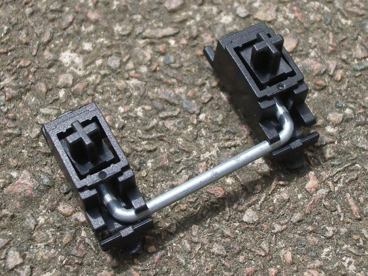

A tiny amount of suitable grease on the wire contact points can reduce tick and friction. Keep lubricant away from electrical contacts, LED openings, and the switch stem path. If the stabilizer is dry but otherwise correct, lubrication is optional. If it binds, remove it and correct the alignment instead of adding more grease.
Step 4: mount the plate and install switches
Hot-swap PCB
- Align the plate with the PCB and stabilizer cutouts.
- Install one switch in each corner and one near the center. These switches hold the plate in position.
- Inspect every switch from below. The metal pins must be straight and the plastic locating pins must align with their holes.
- Press each switch straight down until it is fully seated. Stop immediately if resistance is unusually high.
- Add switches row by row, checking the back of the PCB as you go.
- Retest the board before closing the case. A switch with a bent pin may look installed while failing electrically.
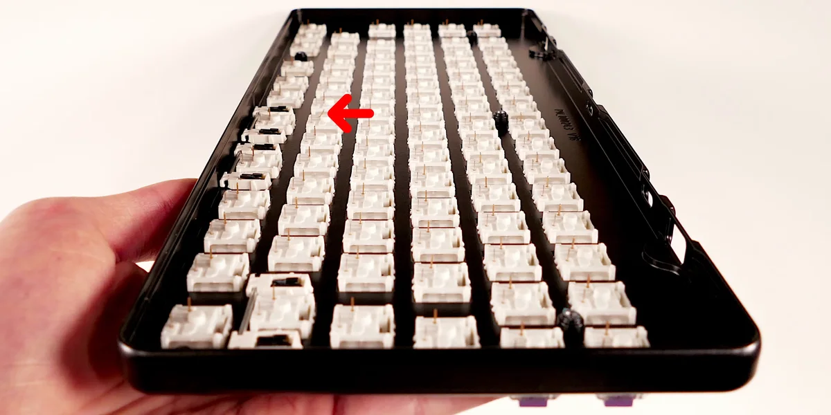

Hot-swap caveat: Repeatedly removing switches, or forcing a switch with a bent pin, can pull a socket from the PCB. Support the plate and use a switch puller that releases both clips at the same time.
Soldered PCB
For a soldered build, install a few switches first so the plate and PCB cannot shift. Turn the assembly over, confirm the pins are still through their holes, and solder one joint at a time.
A sound joint is small, shiny, and flows around the pad and pin without forming a bridge to the next contact. Heat the joint briefly, feed a small amount of solder, then remove the solder and iron. Trim excess lead only after the joint has cooled. Do not hold the iron on a pad long enough to lift it.
After every row, inspect for bridges and retest when the board is disconnected. If you need to remove a joint, use a desoldering pump or wick carefully. Do not pull a switch while solder is solid.
Plateless and flex-cut designs
Some boards mount switches directly to the PCB or use a flexible plate. They may require a different order and gentler pressure. Follow the kit instructions instead of forcing the generic plate steps onto a plateless design.
Step 5: install the PCB in the case
Connect the daughterboard cable in the correct orientation, if your board has one. Route it so it cannot be pinched by the case or rub against a sharp edge. Place foam only where the kit expects it. Thick foam can press on sockets, change the flex, or prevent the case from closing.
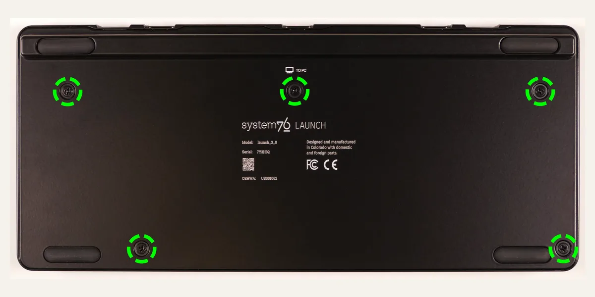
Install the case screws in a cross pattern, turning each one a little at a time. Stop when the case is secure. Over-tightening can strip threads, crack an acrylic case, or eliminate the intended movement of a gasket or flex mount.

Step 6: keycaps and final checks
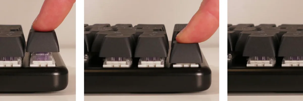
Before pressing on keycaps, confirm the row profile and modifier sizes. Press each cap straight onto the stem. For stabilized keys, fit the wire ends into the keycap inserts first, then press the cap down evenly.

Run this final checklist:
- Every key registers in a keyboard tester.
- VIA or QMK sees the correct layout and saves a test remap, if supported.
- Large keys return evenly and do not tick, bind, or scrape.
- No switch rocks because its pins are bent or its plate clip is incomplete.
- USB, daughterboard, reset, and indicator functions work as documented.
- Case screws are secure without crushing foam or gaskets.
First-build troubleshooting
A key does not register
Remove the keycap and switch. On a hot-swap board, inspect and straighten the pins, then reinstall the switch straight down. If the socket still fails, retest the bare PCB. On a soldered board, inspect the two joints for a cold joint or bridge with the cable disconnected.
A whole row or column fails
Check the firmware layout and connector first. Then inspect for a damaged trace or solder bridge. Several simultaneous failures are rarely caused by several unrelated switches.
The spacebar rattles or feels stiff
Check that the stabilizer wire is fully seated, the housings are aligned, and the keycap is not warped. Remove excess grease before adding more. A crooked wire needs correction, not heavier lubrication.
The case will not close
Stop tightening. Check for a trapped cable, a misplaced foam layer, a switch not fully seated, or a screw in the wrong hole. The case should close with gentle, even pressure.
Must-haves versus enthusiast upgrades
Must-haves: compatible parts, a data-capable cable, the correct firmware instructions, a keycap puller, a well-lit workspace, and time to test. A soldered build additionally needs suitable soldering equipment.
Useful upgrades: a switch puller for hot-swap boards, better stabilizers, pre-cut foam, a switch opener, and a small organizer for parts.
Wait until you know your preferences: premium cables, switch films, extensive foam stacks, alternate plates, artisan keycaps, and large lubricant collections. None of them fixes an incompatible layout or a faulty PCB.
Related guides
- Keyboard anatomy explains what the PCB, plate, case, and mounting system each do.
- Introduction to modding covers reversible sound and feel changes after the board works.
- Keycap materials and profiles helps you choose caps that fit your layout and typing style.
- Essential keyboard accessories separates useful tools from enthusiast extras.
Build slowly, test often, and leave the irreversible work until you understand the board in front of you. That habit makes the second keyboard much easier.